
This page preserves the complete identification and module-location material from the supplied eight-pin chip document, including all associated photographs. The marking list and MCU appendix are preserved on the companion marking page.
Detailed explanation of the 8-pin chip, remember the mask of the chips
Q:What is an eight-pin chip?
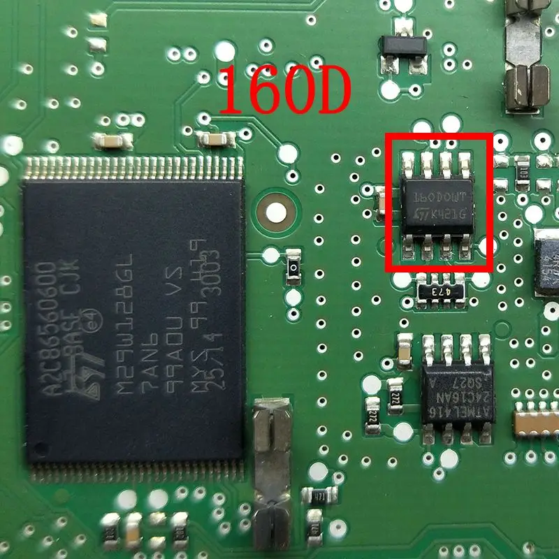
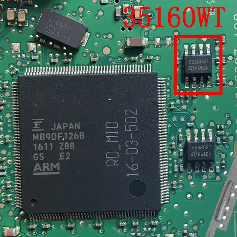
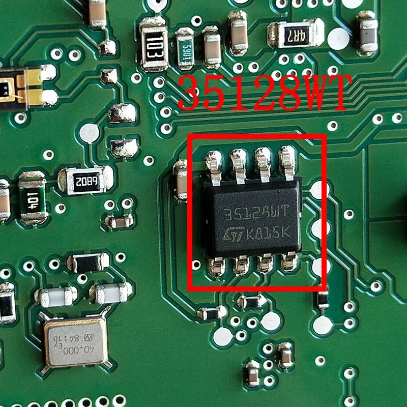
A:There are two styles of eight-pin chips: square and rectangular, which can be further divided into direct-insert and surface-mount types, with 4 antennas on each side. This type of chip has a small data storage capacity and is easy to replace, but it tests welders and requires our patience. Common eight-pin chips include: 24C04, 24C08, 24C16, 24C32, 25020, 25160, 25320, 25640, 25256, 93C66, 93C76, 93C86, 93A86, 95160, 95320, 95640, 95256, 35080, 160D, 35160WT, 35128WT, etc.
Q:What modules are eight-pin chips mostly used for?
A:In our daily work, eight-pin chips are mostly used for instrument clusters and airbag computers, and some are used for other body computers, but most of our customers use them for mileage repair and airbag repair.
Q:Why is it difficult to distinguish or find the location of the eight-pin chip?
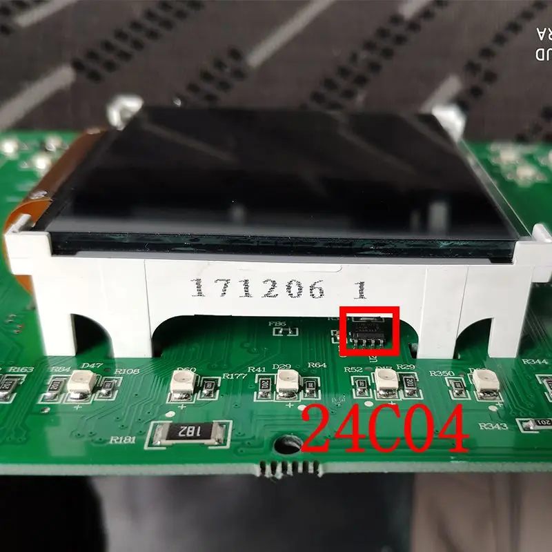
A:This situation often occurs in instrument modules. Usually, the CPU and eight-pin chip of such instruments coexist, either close to each other, on the other side, or even under the display screen. The position is not fixed, and the chip is engraved with a mask. For customers who are new to the industry, they only know the full name of the chip and know nothing about the mask, which tests our eyesight.
1 8-pin chip introduction
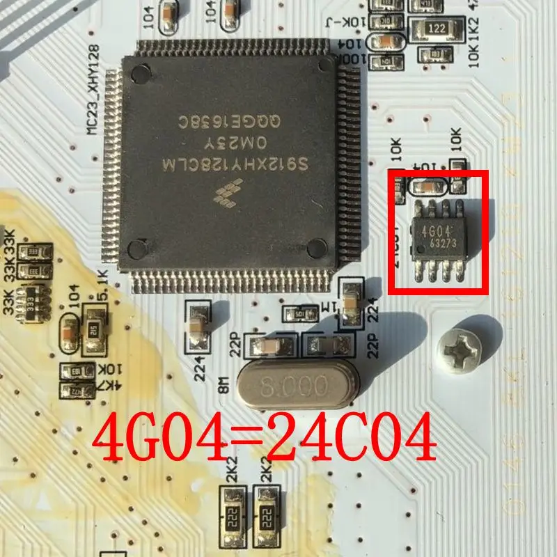
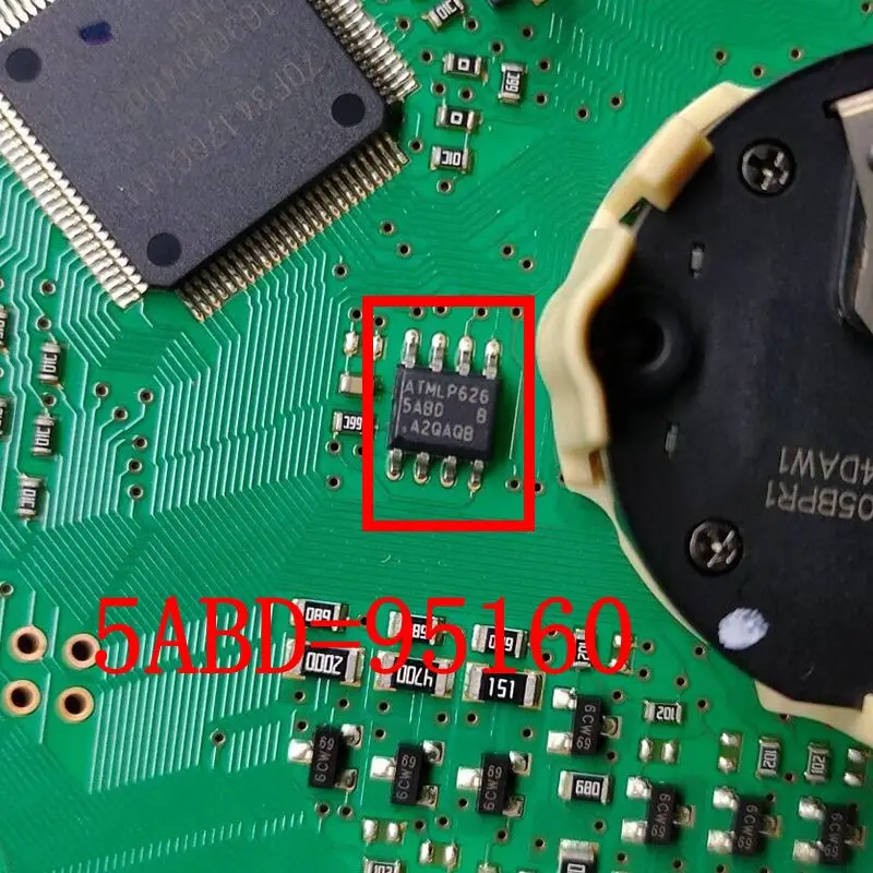
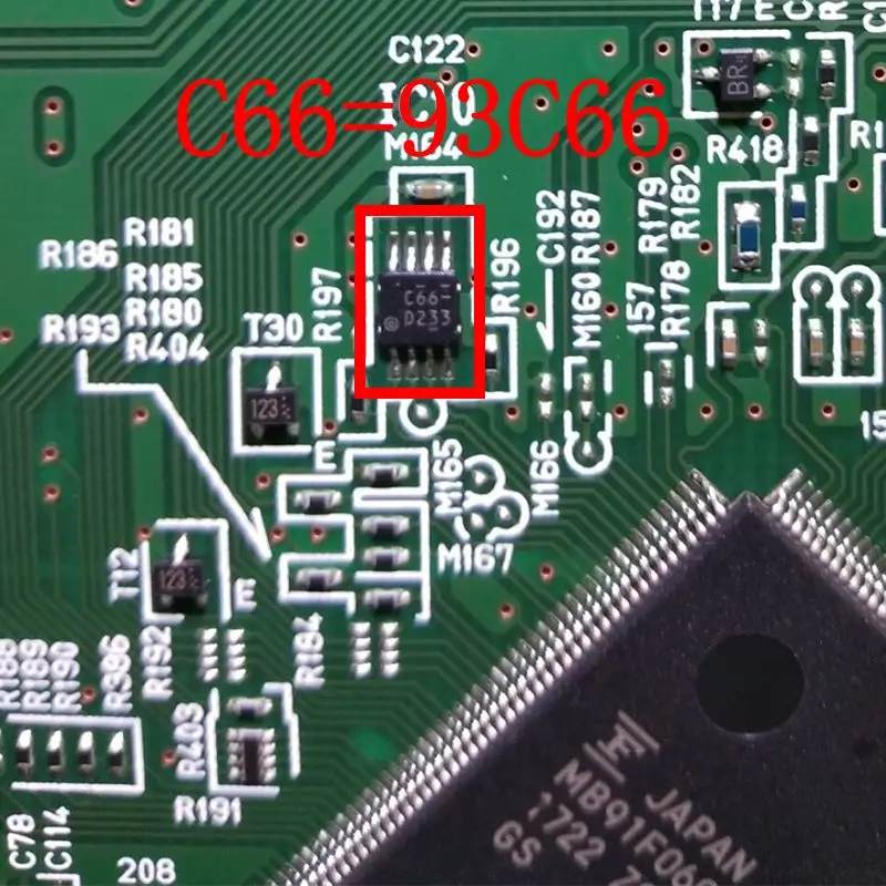
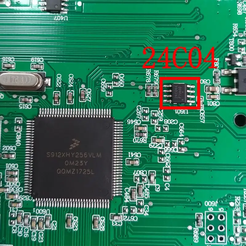
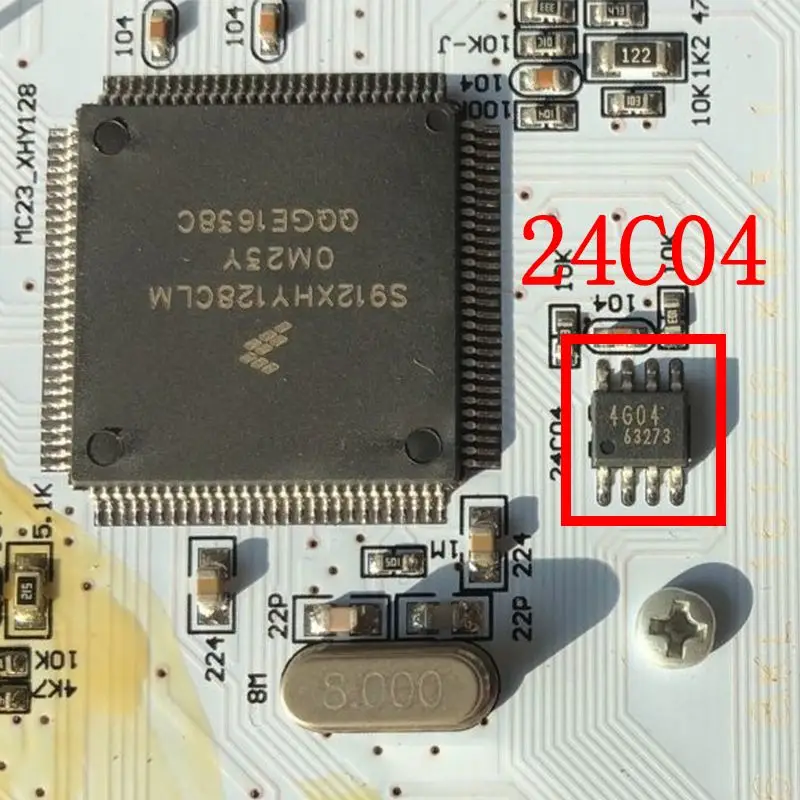
The eight-pin chip is either marked with the full model name or only marked with the mask, so we must remember the corresponding mask name to use it freely. There are three pictures below, the first one is 24C04 , the second one is 95160 , and the third one is 93C66 .
Section 2: complete original EEPROM marking table
3. Determination of chip pin
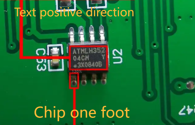
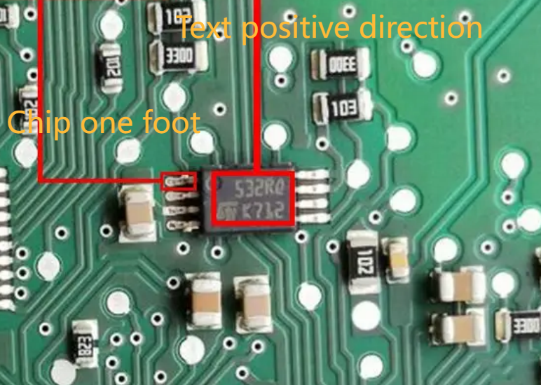
As mentioned before, the overall style of eight-pin chips is divided into square and rectangular, and the pins of these two shapes are definitely different. The square chip has the text facing us, and the lower left is the pin; the rectangular chip has the text facing us, and the upper left is the pin . Based on this standard, we can find the pin of all eight-pin chips. The first picture below is a square eight-pin chip, and the second picture is a rectangular eight-pin chip.
4 8-pin chip in the car module
01 Eight-pin hidden on the instrument
Often, the CPU and the eight-pin chip coexist on the meter, but the eight-pin chip is not clearly marked, and sometimes even on the other side, and the CPU data is empty. The mileage of such a meter is stored in the eight-pin chip, which requires us to have strong eyesight and operational proficiency. Here are some examples of meters so that we can quickly find the eight-pin chip.
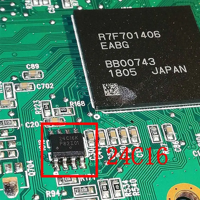
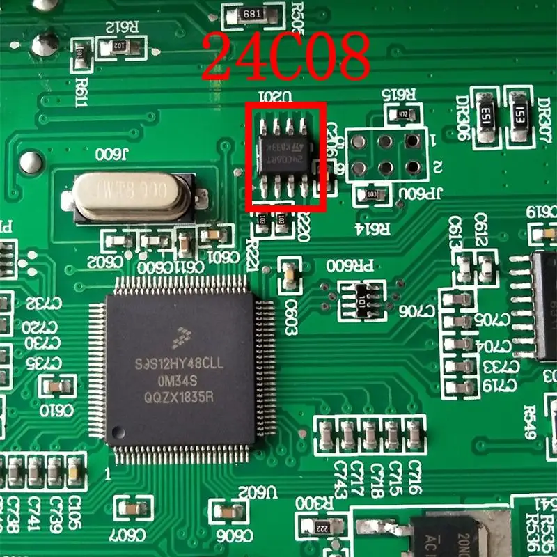
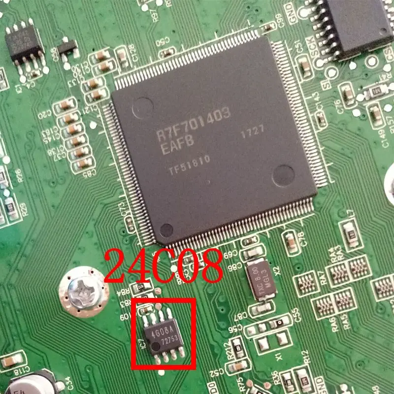
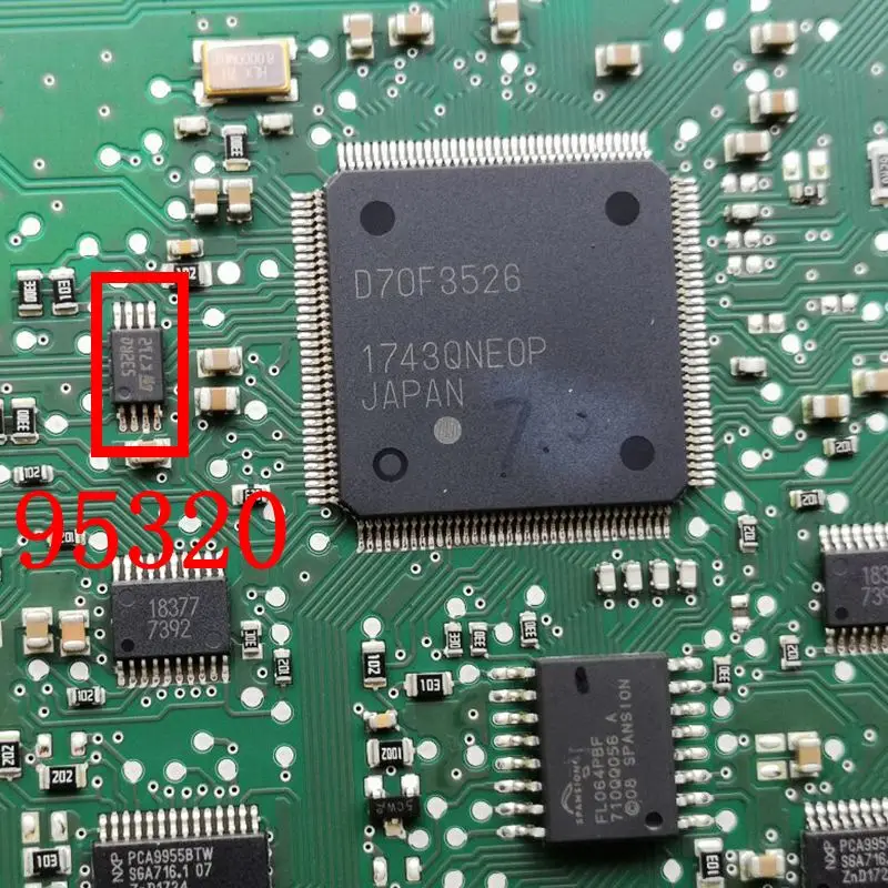
5 Synchronization of instrument and BCM
When some vehicles are repairing their mileage, it is found that after operating the instrument, the mileage will still be adjusted back. In this case, the body data must also be repaired. The instrument and body store the mileage at the same time, and both modules must be operated. Below we have made a table of the models that need to synchronize the instrument and body for your convenience, and you are also welcome to add to it.
| Vehicle | Instrument cluster chip | BCM chip |
|---|---|---|
| BAIC BJ20 | 9S12XHZ512 | 95320 |
| BAIC BJ40 | 9S12XHY256 | 95320 |
| BAIC E130 | 9S12HZ128 | 24C16 |
| BAIC E150 | 9S12HZ128 | 24C16 |
| BAIC D20 | 9S12XHY128 | 24C16/95320 |
| BAIC X25 | 24C16 | 95320 |
| BAIC X35 | 24C16 | 95320 |
| BAIC X55 | 9S12XHY256 | 95320 |
| BAIC X65 | 9S12XHY256 | 95320 |
| BAIC S50 | 9S12XHY256 | 95320 |
| Changhe Q35 | 24C16 | 95320 |
| MG3 | 9S12HZ128 | 24C16/95160 |
| MG3 | 9S12XHZ256 | 24C16 |
| MG5 | 95080 | 24C16/95160 |
| MG6 | 95320 | 95640 |
| MG6 | 080D | 160D |
| ZS | 9S12XHZ512 | 24C16 |
| GT | 9S12XHZ256 | 24C16/95160 |
| GS | 9S12XHZ512 | 24C16/95640 |
| Roewe 350 | 95040 | 24C16/95160 |
| Roewe 350 | 95080 | 24C16 |
| Roewe 360 | 9S12XHZ256 | 24C16/95160 |
| Roewe 550 | 080D | 160D |
| Roewe i6 | 25320 | 95640 |
| Roewe RX3 | 25160 | 95320 |
| Roewe RX3 | 9S12XHZ512 | 95320 |
| Roewe RX5 | 25320 | 24C16 |
| Roewe W5 | 9S12HY64 | 24C16 |
| Peugeot 301 | 93C86 | 25256 |
| Peugeot 307 | 95020 | 95128 |
| Peugeot 308 | 93C86/95020 | 95128 |
| Peugeot 308S | 93C86 | 25256 |
| Citroen C5 | 93C76 | 95128 |
| Citroën C-Elysée | 93C86 | 25256 |
6 Eight-pin chip on the airbag computer
In fact, the eight-pin chip on the airbag computer is easy to find. It is just engraved with a mask and coated with a lot of waterproof glue. The most convenient way is to enter the software to query the airbag number to get the corresponding chip model. The remaining steps are to scrape the chip clean and compare it with the chip mask table.
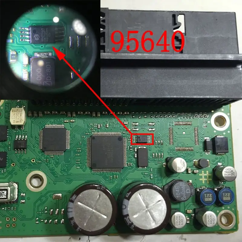
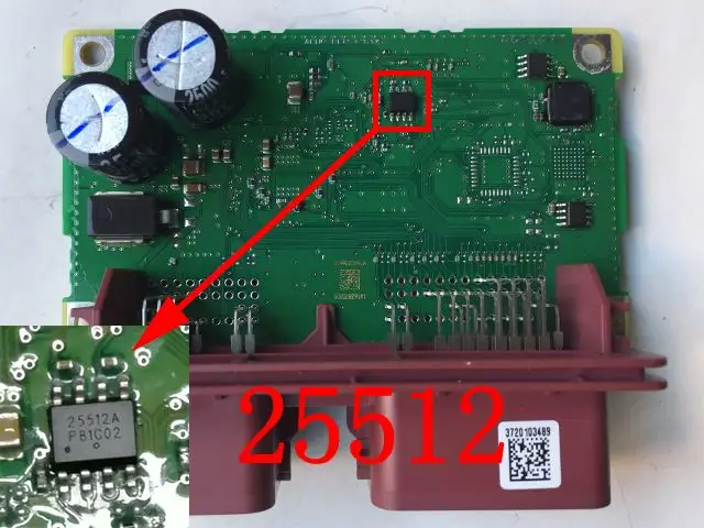
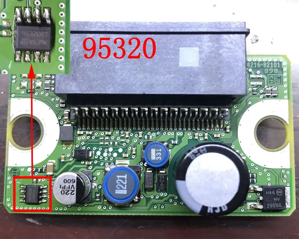
It is not an easy task to identify various eight-pin chips. We need to contact various vehicle modules. The first step is to remember the mask table, and then we can use it freely.
Chip welding also requires our special attention. Many customers often break the chip pins due to excessive force or too long soldering time, resulting in data loss. Even if you are very skilled, I hope everyone will take their time to ensure that nothing goes wrong!
Section 7: original MCU mask-code appendix
Open the HC/9S12 text entries in the MCU appendix
Manufacturer checks
Use the Microchip 93xx46 datasheet and ST M24C04 datasheet for the device-specific voltage, organisation and pin-assignment checks for the specific device.